- Harness Routing Instructions
- Detailed Colored Wiring Diagram
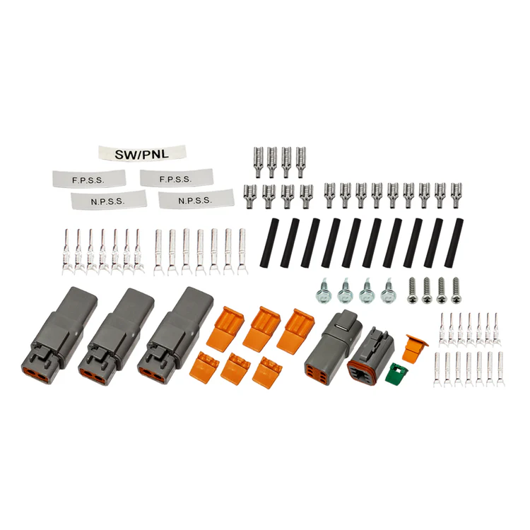
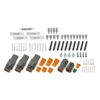
- Deutsch Connectors
- High Quality Molex Terminals
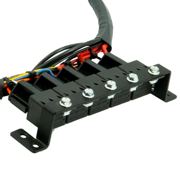
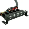
- Covered Fuse Box with LED Illumination
- Bueler 40/60 Amp Relays
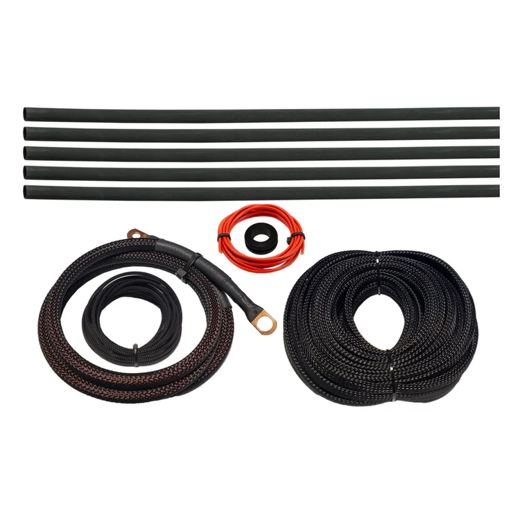
- Protective Expandable Wiring Loom
- Automotive Copper Core Wire with Protective Silicone Coating
Operation Components:
Single Stage Nitrous System, Transbrake Interrupt, Purge Kit, Bottle Heater, Heater Pressure Switch, Fuel Pressure Safety Switch, Timing Output, & WinMax Nitrous Controller
Harness Components:
Harness Routing Instructions
Detailed Colored Wiring Diagram
Deutsch Connectors
High Quality Molex Terminals
Covered Fuse Box with LED Illumination
Bueler 40/60 Amp Relays
Protective Expandable Wiring Loom
Detailed Colored Wiring Diagram
Deutsch Connectors
High Quality Molex Terminals
Covered Fuse Box with LED Illumination
Bueler 40/60 Amp Relays
Protective Expandable Wiring Loom
Automotive Copper Core Wire with Protective Silicone Coating
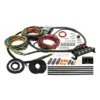
The Nitrous Outlet Universal DIY professional wiring harness is designed to work in conjunction with the Nitrous Outlet WinMax controller and is the perfect option to simplifying the wiring process associated with nitrous installations.
The most time consuming and complicated part of the wiring process is eliminated with the detailed instructions, colored wiring schematics, pin out sheet, and universally mounted pre wired relay pack with fuse panel.
The Harness is separated into three groups for ease of routing to the Engine bay components, interior dash components, and bottle location components .
Installation requires 7 easy steps
Step 1:Â Determine location and mount the Relay pack and fuse panel.
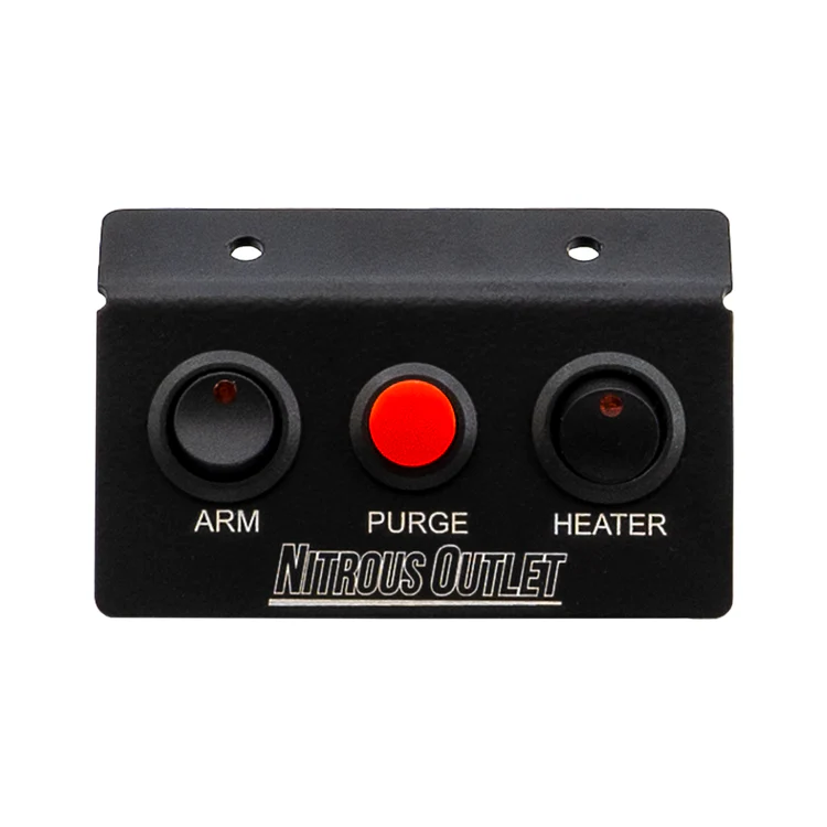
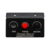
Step 2:Â Mount the Switch Panel.
Step 3:Â Route the wiring to the system components.
Step 4:Â Cover the wire with the protective expandable wiring loom.
Step 5:Â Cut the wire to length
Step 6:Â Terminate the wiring ends and connect to the system components.
Step 7:Â Connect Harness Power, Ground, Keyed hot, tach signal, and TPS signal or WOT switch.
Reviews
There are no reviews yet.